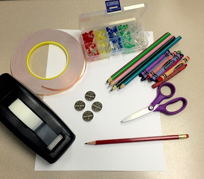
My last school-aged STEAM program of the summer focused on electrical circuits. Unlike previous programs, this one required some specialized supplies that are not readily available locally, but are relatively low-cost and easily ordered online. All you need is copper tape, small LED lights, button batteries, cardstock, scotch tape, and markers, pencils, and/or crayons. These can be used to build a circuit on a piece of paper or cardboard, and could be applied to a number of different projects, but I decided to have the kids use the circuits to light up their own artwork.
Recommended Ages: 8-14
Recommended Group Size: 10-20; this is definitely better with a smaller group
Time: 1 hour for main project, additional 15-30 minutes for exploring with the Touch Circuits
Budget: About $35 for consummable supplies [with plenty leftover for future programs], $25 for each Touch Circuit toy.
To demonstrate how a circuit works, I started with a demonstration using these really neat educational toys from Lakeshore called "Light and Sound Touch Circuits". It is a "stick" with a handle that acts as a terminal at each end. When the circuit is completed, the "stick" lights up and plays sounds (the sounds can be turned off if desired). The circuit can be completed by one person holding each handle, or by two or more people in a chain. I started with showing them with two of us, then three, then the whole class. They got to see how it would stop anytime someone broke the circuit, and I told them to keep that in mind later if they had to trouble-shoot their project.
Next I showed them the paper circuits, first a simple circuit with one light, then series and parallel circuits with two lights. I explained to them the advantage of parallel was that you could still power two lights with one battery, while the series circuit required two batteries, and that if one light went out, the other light would still work in a parallel circuit. They got to look at them up close, and see the two different methods of making a on-off switch.
* I also made sure to warn them about safety regarding the button batteries. They are very dangerous if swallowed and must be kept away from younger siblings and pets!*
Materials & Supplies
- 1/4" Copper Tape with conductive adhesive about 12-18" per participant
- small LED lights, 3mm or 5mm, assorted colors if desired, 2 per participant
- 3V button battery, 2032 or 2016 (warn about safety)
- Cardstock
- Scotch tape
- scissors
- markers, colored pencils, and/or crayons
- regular pencil
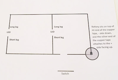
1. Because our group usually skews younger, I pre-printed a parallel circuit template on cardstock for them and folded the top half of the cardstock down over the circuit template. I showed them how to hold it up to the light or window so you can see through and lightly mark where the LED's will be. [For older kids, I would let them plan and draw their circuit templates themselves.]
Then I told them to use their imaginations and think about how they could incorporate the lights into a drawing, such as lights on a bridge or building, fireflies, stars, lights on a vehicle, space ship, etc., then make their picture.
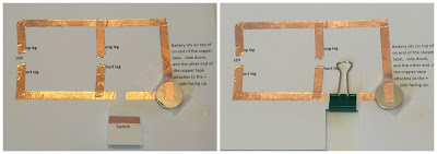
2. Carefully measure and cut the pieces of copper tape and apply to the template, being sure to leave the indicated gaps, and get it as smooth as possible. Be sure to get complete overlap at all corners and intersections and smooth down well for best conductivity. Begin where the battery will be, then set the battery in place (+) side UP, and end the last piece of copper tape by attaching it to the top of the battery. Use scotch tape to secure the battery in place.
(Ideally, the tape would be applied in as few pieces as possible, using a precise fold to turn the corners rather than cutting separate pieces. While this creates a more efficient circuit, it is tricky and I felt would be too difficult for the ages that I had.)
3. For the switch, put a small piece of copper tape on the indicated line, then cut on either side so it can fold up over the gap in the circuit and complete the circuit. Use a binder clip to hold in place if desired. (There are other types of on/off controls and some more sophisticated battery holders you can find described online that you might want to try).
4. Place the LED's. Look closely at the LED; the positive leg is the one that is slightly longer. Be sure to keep up with which one it is, and bend each leg out at a 90 degree angle. Place the LEDs in the designated gaps in the circuit, pointing the longer, (+) leg in the direction of the (+) side of the battery, and tape in place.
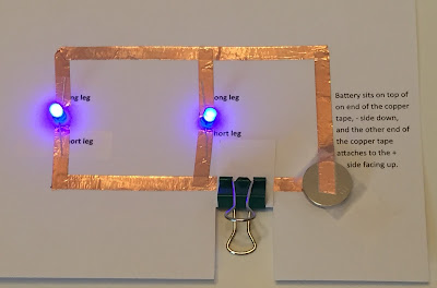
5. If the switch is in the "ON" position, the LED's should light up once they are in place. Depending on lighting effect desired, poke a hole for the bulb to go through if a bright light is desired, or not if a more gentle glow is desired.
Here are some examples I made (unfortunately didn't get any pictures of any the kids made):
Troubleshooting
1. The most common problem are loose or inefficient connections. Be sure the battery is connected with the copper tape at both ends of the circuit, make sure there are no gaps where two pieces of tape come together, but a complete overlap, make sure the switch is fully bridging the gap and connecting at each end. Because this is on paper, the flexible nature will cause some fluctuations and flickering, especially when picked up. This is to be expected.
2. The second most common problem is the LED put in backwards, or the battery upside down.
3. Also, both LED's and branches of the circuit must have the same resistance for the current to split and light both of them. Since current will seek the path of least resistance, only one will light up if it has even a slightly lower resistance than the other. It is safest to use the same color LED for both lights, but that is not a guarantee. If this causes too much frustration, you can stick with a simple circuit with just one LED (probably best for younger kids).
After they were finished with their paper circuits, we got out the rest of the Touch Circuit toys (we have 10) and let them experiment with them. They discovered they could test the conductivity of different materials by working with a partner and each of them holding one end of the Touch Circuit stick, then each holding an end of the material to be tested with their other hands. The kids loved them and I highly recommend them! My manager saw them being demonstrated at a local conference we were presenting at and knew we had to have them.
Here is a really quick and dirty (i.e., crappy) video I made to briefly demonstrate how these work:
How It Went
The kids that had been there the previous time we came for the DNA program were excited to see us walk in, and all of them really seemed to enjoy this program, and had less trouble building their circuits that I thought they would. Some of them caught on really quickly, and did a great job helping out the others. Only the very youngest child needed a significant amount of help, which was not suprising as he was only barely 6, and maybe slightly immature for 6. He did need one-on-one instruction, but fortunately there were 3 of us, so we each took turns helping him as well as checking on everyone else's progress and answering questions and troubleshooting. They REALLY loved playing with the touch circuits afterwards, and their teacher told their director they needed to buy some. The teacher asked the kids what they would rate the program on a scale on 1 to 10, and I was very happy to hear unanimous 10's!
So that will probably be it for school-aged programming until next Spring Break, back to focusing on early literacy and storytime!


No comments:
Post a Comment